8.1 KiB
@defgroup boards_esp32_ttgo-t-beam TTGO T-Beam @ingroup boards_esp32 @brief Support for TTGO T-Beam boards @author Yegor Yefremov yegorslists@googlemail.com
\section esp32_ttgo_t_beam TTGO T-Beam
Table of Contents
Overview
TTGO T-Beam is an ESP32 development board with 4 MB Flash that uses the EPS32 chip directly. It integrates:
- a SemTech SX1276 or SX1278 for LoRaWAN communication
- a U-Blox Neo-6M GPS receiver
There are at least three board types: rev0, rev1, and V1.0. Versions rev0 and rev1 are very similar, the only difference is that rev1 has an additional LED connected to GPIO14. The pinout of V1.0 has more changes thus it is necessary to add the following line to the makefile of the application to use the according configuration for TTGO T-Beam V1.0:
USEMODULE += esp32_ttgo_t_beam_v1_0
Hardware
This section describes
- the MCU,
- the default board configuration,
- optional hardware configurations,
- the board pinout.
MCU
Most features of the board are provided by the ESP32 SoC. For detailed information about the ESP32, see section \ref esp32_mcu_esp32 "MCU ESP32".
Board Configuration
TTGO T-Beam has the following on-board components:
- SemTech SX1276 or SX1278 for LoRaWAN communication
- U-Blox Neo-6M GPS receiver
There are two hardware versions of the board:
- SemTech SX1278 for LoRaWAN communication in the 433 MHz band
- SemTech SX1276 for LoRaWAN communication in the 868/915 MHz band
Since many GPIOs are broken out, they can be used for different purposes in different applications. For flexibility, some GPIOs might be listed in various peripheral configurations. For example, GPIO0 is used in the ADC channel definition \ref ADC_GPIOS and the PWM channel definition \ref PWM0_GPIOS.
This is possible because GPIOs are only used for a specific peripheral interface when
- the corresponding peripheral module is used, e.g., module
periph_i2c, or - a corresponding init function is called e.g., \ref adc_init, \ref dac_init and \ref pwm_init, or
- the corresponding peripheral interface is used for the first time, e.g., \ref spi_acquire.
That is, the purpose for which a GPIO is actually used depends on which module or function is used first.
@note GPIOs 5, 12, 15, 16, 17, 18, 19, 26, and 27 are used for board control functions and should not be used for other purposes unless you exactly know what you are doing.
The following table shows the default board configuration, which is sorted according to the defined functionality of GPIOs. This configuration can be overridden by \ref esp32_application_specific_configurations "application-specific configurations".
TTGO- T-Beam rev1
Function | GPIOs | Remarks |Configuration :---------------|:-------|:--------|:---------------------------------- BUTTON0 | GPIO39 | low active | | LED0 | GPIO14 | high active | | ADC | GPIO0, GPIO2, GPIO4, GPIO13,\n GPIO25, GPIO32, GPIO33, GPIO35,\n GPIO36, GPIO34 | | \ref esp32_adc_channels "ADC Channels" DAC | GPIO25 | | \ref esp32_dac_channels "DAC Channels" PWM_DEV(0) | GPIO14, GPIO0, GPIO2, GPIO25 | | \ref esp32_pwm_channels "PWM Channels" I2C_DEV(0):SDA | GPIO21 | | \ref esp32_i2c_interfaces "I2C Interfaces" I2C_DEV(0):SCL | GPIO22 | I2C_SPEED_FAST is used | \ref esp32_i2c_interfaces "I2C Interfaces" SPI_DEV(0):CLK | GPIO5 | VSPI is used | \ref esp32_spi_interfaces "SPI Interfaces" SPI_DEV(0):MISO | GPIO19 | VSPI is used | \ref esp32_spi_interfaces "SPI Interfaces" SPI_DEV(0):MOSI | GPIO27 | VSPI is used | \ref esp32_spi_interfaces "SPI Interfaces" SPI_DEV(0):CS0 | GPIO18 | VSPI is used | \ref esp32_spi_interfaces "SPI Interfaces" UART_DEV(0):TxD | GPIO1 | Console (configuration is fixed) | \ref esp32_uart_interfaces "UART interfaces" UART_DEV(0):RxD | GPIO3 | Console (configuration is fixed) | \ref esp32_uart_interfaces "UART interfaces" UART_DEV(1):TxD | GPIO15 | GPS (configuration is fixed) | \ref esp32_uart_interfaces "UART interfaces" UART_DEV(1):RxD | GPIO12 | GPS (configuration is fixed) | \ref esp32_uart_interfaces "UART interfaces"TTGO- T-Beam V1.0
Function | GPIOs | Remarks |Configuration :---------------|:-------|:--------|:---------------------------------- BUTTON0 | GPIO38 | low active | | ADC | GPIO0, GPIO2, GPIO4, GPIO13,\n GPIO25, GPIO32, GPIO33, GPIO35,\n GPIO36, GPIO39 | | \ref esp32_adc_channels "ADC Channels" DAC | GPIO25 | | \ref esp32_dac_channels "DAC Channels" PWM_DEV(0) | GPIO14, GPIO0, GPIO2, GPIO25 | | \ref esp32_pwm_channels "PWM Channels" I2C_DEV(0):SDA | GPIO21 | | \ref esp32_i2c_interfaces "I2C Interfaces" I2C_DEV(0):SCL | GPIO22 | I2C_SPEED_FAST is used | \ref esp32_i2c_interfaces "I2C Interfaces" SPI_DEV(0):CLK | GPIO5 | VSPI is used | \ref esp32_spi_interfaces "SPI Interfaces" SPI_DEV(0):MISO | GPIO19 | VSPI is used | \ref esp32_spi_interfaces "SPI Interfaces" SPI_DEV(0):MOSI | GPIO27 | VSPI is used | \ref esp32_spi_interfaces "SPI Interfaces" SPI_DEV(0):CS0 | GPIO18 | VSPI is used | \ref esp32_spi_interfaces "SPI Interfaces" UART_DEV(0):TxD | GPIO1 | Console (configuration is fixed) | \ref esp32_uart_interfaces "UART interfaces" UART_DEV(0):RxD | GPIO3 | Console (configuration is fixed) | \ref esp32_uart_interfaces "UART interfaces" UART_DEV(1):TxD | GPIO34 | GPS (configuration is fixed) | \ref esp32_uart_interfaces "UART interfaces" UART_DEV(1):RxD | GPIO12 | GPS (configuration is fixed) | \ref esp32_uart_interfaces "UART interfaces" \n@note
- The configuration of ADC channels contains all ESP32 GPIOs that can be used as ADC channels.
For detailed information about the configuration of ESP32 boards, see section \ref esp32_peripherals "Common Peripherals".
Board Pinout
The following figures show the pinout of the defined default configurations for TTGO T-Beam boards.
@image html "https://ae01.alicdn.com/kf/HTB1OhPmXtzvK1RkSnfoq6zMwVXah.jpg" "TTGO T-Beam rev1 Pintout Diagram"
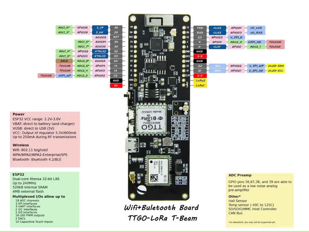
@image html "https://ae01.alicdn.com/kf/Hee7e9a85bb294351952a073325e6b2f96.jpg" "TTGO T-Beam V1.0 Pintout Diagram"
The corresponding board schematics can be found on TinyMicros.com for TTGO T-Beam rev0 and GitHub for TTGO T-Beam V1.0
Flashing the Device
Flashing RIOT is quite easy. The board has a Micro-USB connector with reset/boot/flash logic. Just connect the board to your host computer and type using the programming port:
make flash BOARD=esp32-ttgo-t-beam ...
For detailed information about ESP32 as well as configuring and compiling RIOT for ESP32 boards, see \ref esp32_riot.