6.0 KiB
@defgroup boards_lora-e5-dev LoRa-E5 Development Board - STM32WLE5JC @ingroup boards @brief Support for the LoRa-E5 Development Board - STM32WLE5JC.
@warning This BOARD comes with arduino style pin headers, but the gpio mapping does not map to arduino BOARDs, even 3.3V and 5V pins are placed differently, so don't use arduino expansion-boards since these might short-circuit the mcu and/or expansion-board.
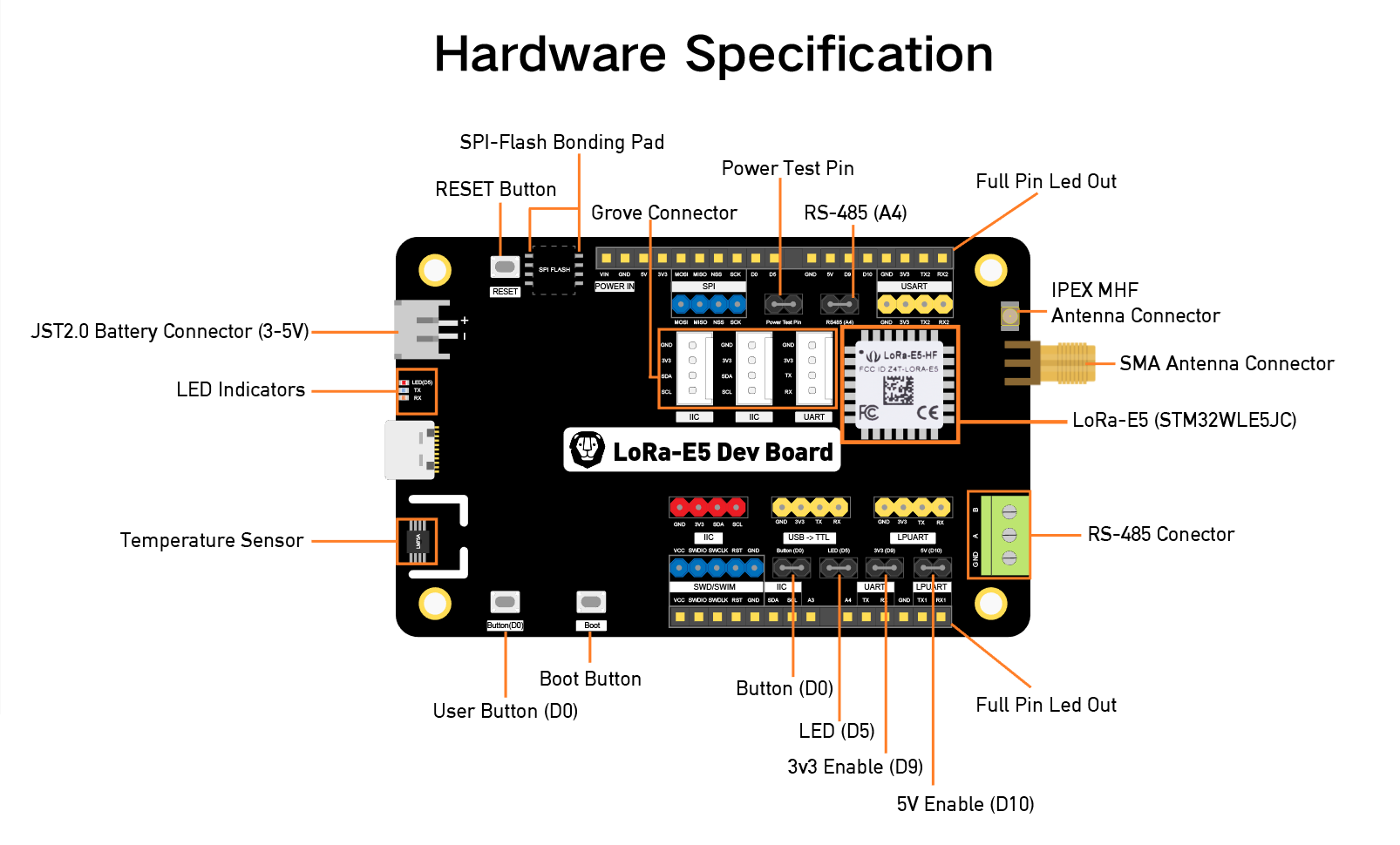
The LoRa-E5 Dev Board is an evaluation board for the Seeed Studio LoRa-E5 STM32WLE5JC module. The cpu includes a radio supporting multiple LPWAN protocols in the 868/915 MHz frequency bands, including LoRa, capable of 20.8dBm output at 3.3V.
Convenient interfaces as Grove and RS-485 are mapped out, and the many pins map most of the modules GPIOs. But watch out! Although it features Arduino style pin headers, they are not arduino compatible.
The board also includes a JST battery connector as well as control over the external power lines which can be enabled or disabled by software.
MCU
| MCU | STM32WL5EJC |
|---|---|
| Family | ARM Cortex-M4 |
| Vendor | ST Microelectronics |
| RAM | 64KiB |
| Flash | 256KiB |
| Frequency | up to 48MHz |
| FPU | no |
| Vcc | 1.8 V - 3.6V |
| Datasheet | Datasheet |
| Reference Manual | Reference Manual |
| Board Manual | Board Manual |
| Board Schematic | Board Schematic |
| LoRa-E5 STM32WL5EJC Module wiki | https://wiki.seeedstudio.com/LoRa-E5_STM32WLE5JC_Module/#2-develop-with-stm32cube-mcu-package |
Pinout
The default Peripheral Mapping is specified here
Board Interface
3 Buttons:
| NAME | BOOT | D0 | RESET |
|---|---|---|---|
| Pin | PA0 (IN) | PB13 (IN) | NRST |
1 LED:
| NAME | D5 |
|---|---|
| Color | red |
| Pin | PB5 |
Power Lines
All power lines are on by default, but some of them can optionally be disabled, namely 3.3V and 5V. These feed all external pins as well as the internal LM75A, more details are available on the schematic.
| Name | Controlled By | Alias |
|---|---|---|
| 3.3V | PA9 | LORA_E5_DEV_3P3V_ENABLE_PIN |
| 3.3V | PB10 | LORA_E5_DEV_5V_ENABLE_PIN |
Flashing
Disabling Read Protection
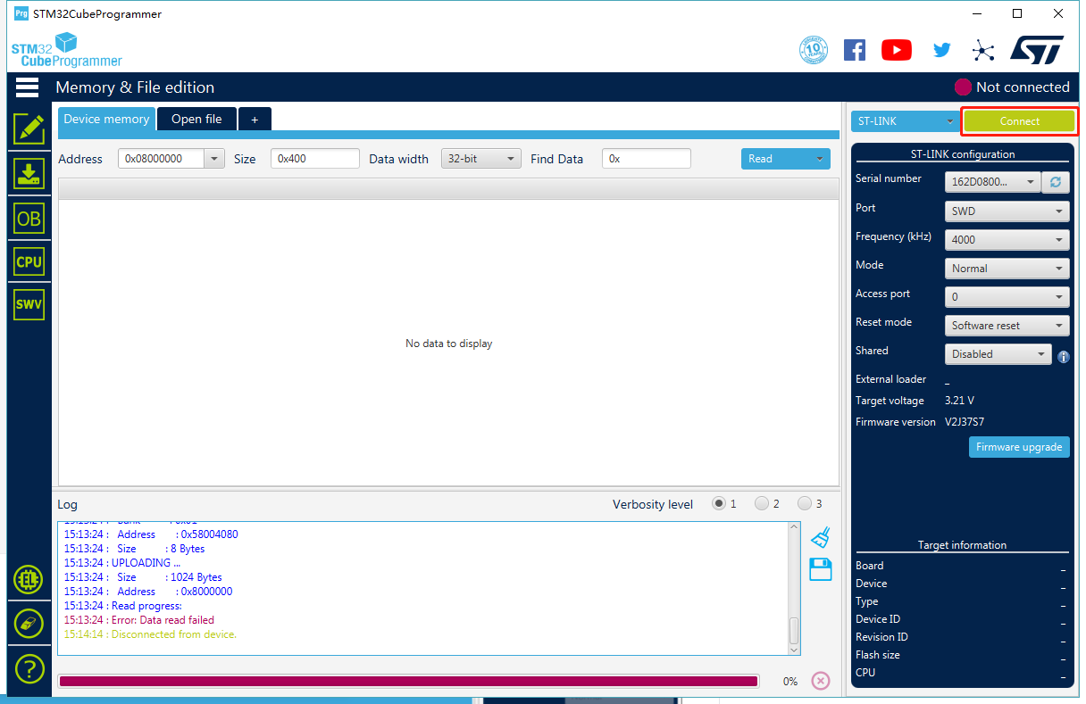
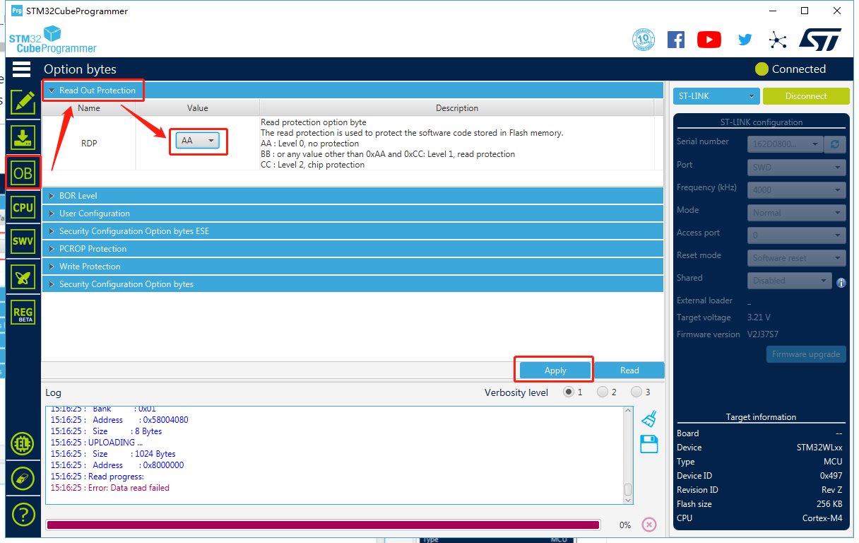
The board comes pre-flashed with a DFU bootloader, an AT command Firmware and read protection enabled and set to 1. So before being able to program anything else, read protection needs to be set back to level 0.
The easiest way of doing this is with the STM32CubeProgramer
GUI and setting the RDP option byte to AA
Alternatively you can use the STM32_Programer_CLI:
$ STM32_Programmer_CLI --connect port=swd --readunprotect
Programming with an external ST-LINK
Since there is no ST-LINK programmer on the board an external one needs to be connected. Any Nucleo or STM32Discovery board can be used for this by simply removing the ST-LINK jumpers and connecting on the CN4 headers (see UM1724 6.2.4 for more details). An example is seen in the following image:

     CN4                                       LoRa-E5 Dev
                                            (Dark Blue Header)
Pin 1: VDD_TARGET            N/C
Pin 2: SWCLK      ---->  Yellow Cable ---->       CLK
Pin 3: GND        ---->  Black Cable  ---->       GND
Pin 4: SWDIO      ---->  Blue Cable   ---->       DIO
Pin 5: NRST                  N/C
Pin 6: SWO                   N/C
Flashing can then be performed seamlessly with OpenOCD:
BOARD=lora-e5-dev make flash
Serial connection
The default serial connection is through the USB-C port mapping to PB7 (RX) and PB6 (TX) UART pins (a second UART and an LPUART interface is also exposed).
BOARD=lora-e5-dev make term
Debugging
For Debugging an external programmer is required, connected as depicted in the above picture, then the debugger can be attached with:
BOARD=lora-e5-dev make debug
LoRa
This board comes embedded with an sx126x based LoRa radio. The precise
module that needs to be selected is USEMODULE += sx126x_stm32wl, this
is also selected with USEMODULE += netdev_default.
Differently from other stm32wl chips this module only transmits through
RFO_HP.
Sensors
This board includes a @ref drivers_lm75 temperature sensor. It can be
included with USEMODULE += lm75a or through USEMODULE += saul_default.