mirror of
https://github.com/RIOT-OS/RIOT.git
synced 2025-12-19 03:23:49 +01:00
147 lines
6.0 KiB
Markdown
147 lines
6.0 KiB
Markdown
@defgroup boards_lora-e5-dev LoRa-E5 Development Board - STM32WLE5JC
|
|
@ingroup boards
|
|
@brief Support for the LoRa-E5 Development Board - STM32WLE5JC.
|
|
|
|
@warning This BOARD comes with arduino style pin headers, but the gpio
|
|
mapping does not map to arduino BOARDs, even 3.3V and 5V pins
|
|
are placed differently, so don't use arduino expansion-boards
|
|
since these might short-circuit the mcu and/or expansion-board.
|
|
|
|
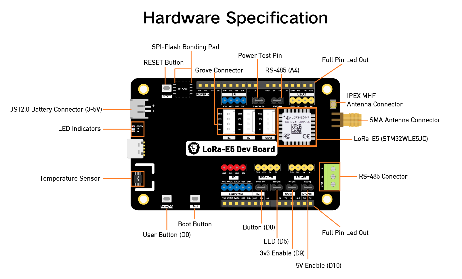
The LoRa-E5 Dev Board is an evaluation board for the Seeed Studio LoRa-E5 STM32WLE5JC
|
|
module. The cpu includes a radio supporting multiple LPWAN protocols in the
|
|
868/915 MHz frequency bands, including LoRa, capable of 20.8dBm output at 3.3V.
|
|
|
|
Convenient interfaces as Grove and RS-485 are mapped out, and the many pins
|
|
map most of the modules GPIOs. But watch out! Although it features
|
|
Arduino style pin headers, they are not arduino compatible.
|
|
|
|
The board also includes a JST battery connector as well as control over the
|
|
external power lines which can be enabled or disabled by software.
|
|
|
|
### MCU
|
|
| MCU | STM32WL5EJC |
|
|
|:---------- |:--------------------------------------------------------- |
|
|
| Family | ARM Cortex-M4 |
|
|
| Vendor | ST Microelectronics |
|
|
| RAM | 64KiB |
|
|
| Flash | 256KiB |
|
|
| Frequency | up to 48MHz |
|
|
| FPU | no |
|
|
| Vcc | 1.8 V - 3.6V |
|
|
| Datasheet | [Datasheet](https://files.seeedstudio.com/products/317990687/res/STM32WLE5JC%20Datasheet.pdf) |
|
|
| Reference Manual | [Reference Manual](https://www.st.com/resource/en/reference_manual/rm0461-stm32wlex-advanced-armbased-32bit-mcus-with-subghz-radio-solution-stmicroelectronics.pdf) |
|
|
| Board Manual | [Board Manual](https://www.st.com/resource/en/data_brief/nucleo-wl55jc.pdf) |
|
|
| Board Schematic | [Board Schematic](https://files.seeedstudio.com/products/113990934/LoRa-E5%20Dev%20Board%20v1.0.pdf) |
|
|
| LoRa-E5 STM32WL5EJC Module wiki | https://wiki.seeedstudio.com/LoRa-E5_STM32WLE5JC_Module/#2-develop-with-stm32cube-mcu-package |
|
|
|
|
### Pinout
|
|
|
|
|
|
|
|
The default Peripheral Mapping is specified [here](https://github.com/RIOT-OS/RIOT/blob/master/boards/lora-e5-dev/include/periph_conf.h)
|
|
|
|
### Board Interface
|
|
|
|
3 Buttons:
|
|
|
|
| NAME | BOOT | D0 | RESET |
|
|
|:------ |:---------|:--------- |:----- |
|
|
| Pin | PA0 (IN) | PB13 (IN) | NRST |
|
|
|
|
1 LED:
|
|
|
|
| NAME | D5 |
|
|
| ----- | ----- |
|
|
| Color | red |
|
|
| Pin | PB5 |
|
|
|
|
### Power Lines
|
|
|
|
All power lines are on by default, but some of them can optionally be disabled,
|
|
namely 3.3V and 5V. These feed all external pins as well as the internal LM75A,
|
|
more details are available on the schematic.
|
|
|
|
| Name | Controlled By | Alias |
|
|
|:---- |:------------- |:--------------------------- |
|
|
| 3.3V | PA9 | LORA_E5_DEV_3P3V_ENABLE_PIN |
|
|
| 3.3V | PB10 | LORA_E5_DEV_5V_ENABLE_PIN |
|
|
| | | |
|
|
|
|
### Flashing
|
|
|
|
#### Disabling Read Protection
|
|
|
|
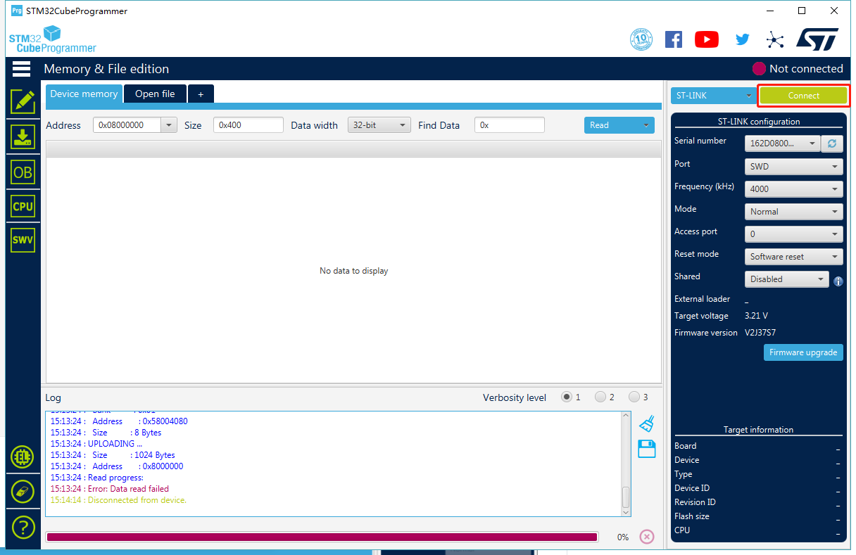
The board comes pre-flashed with a DFU bootloader, an AT command Firmware
|
|
and read protection enabled and set to 1. So before being able to program anything
|
|
else, read protection needs to be set back to level 0.
|
|
|
|
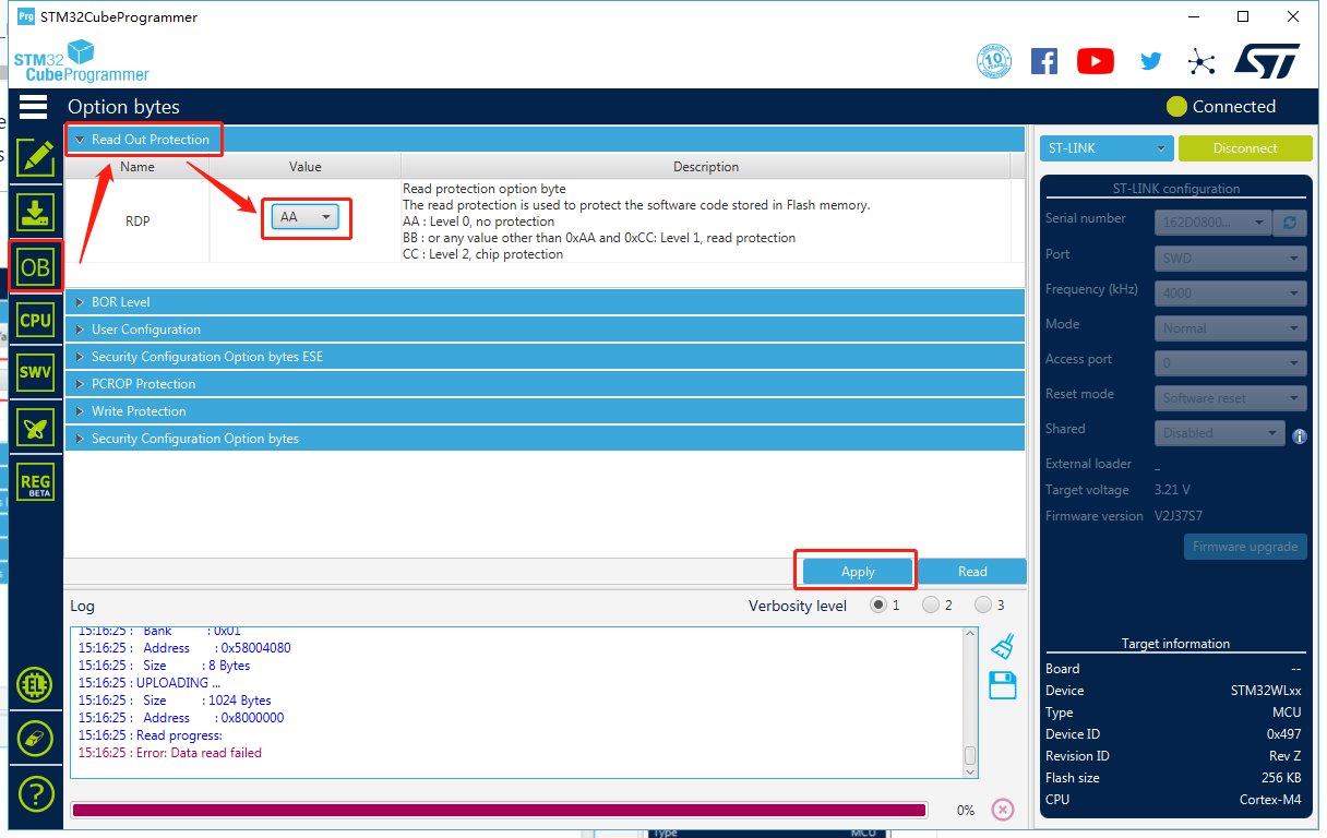
The easiest way of doing this is with the [STM32CubeProgramer](https://www.st.com/en/development-tools/stm32cubeprog.html)
|
|
GUI and setting the RDP option byte to `AA`
|
|
|
|
|
|
|
|
|
|
Alternatively you can use the STM32_Programer_CLI:
|
|
|
|
```
|
|
$ STM32_Programmer_CLI --connect port=swd --readunprotect
|
|
```
|
|
|
|
#### Programming with an external ST-LINK
|
|
|
|
Since there is no ST-LINK programmer on the board an external one
|
|
needs to be connected. Any Nucleo or STM32Discovery board can be used for this
|
|
by simply removing the ST-LINK jumpers and connecting on the CN4 headers
|
|
(see [UM1724 6.2.4](https://www.st.com/resource/en/user_manual/um1724-stm32-nucleo64-boards-mb1136-stmicroelectronics.pdf)
|
|
for more details). An example is seen in the following image:
|
|
|
|

|
|
|
|
```
|
|
CN4 LoRa-E5 Dev
|
|
(Dark Blue Header)
|
|
Pin 1: VDD_TARGET N/C
|
|
Pin 2: SWCLK ----> Yellow Cable ----> CLK
|
|
Pin 3: GND ----> Black Cable ----> GND
|
|
Pin 4: SWDIO ----> Blue Cable ----> DIO
|
|
Pin 5: NRST N/C
|
|
Pin 6: SWO N/C
|
|
```
|
|
|
|
Flashing can then be performed seamlessly with OpenOCD:
|
|
|
|
```
|
|
BOARD=lora-e5-dev make flash
|
|
```
|
|
|
|
### Serial connection
|
|
|
|
The default serial connection is through the USB-C port mapping to PB7 (RX) and
|
|
PB6 (TX) UART pins (a second UART and an LPUART interface is also exposed).
|
|
|
|
```
|
|
BOARD=lora-e5-dev make term
|
|
```
|
|
### Debugging
|
|
|
|
For Debugging an external programmer is required, connected as depicted in
|
|
the above picture, then the debugger can be attached with:
|
|
|
|
```
|
|
BOARD=lora-e5-dev make debug
|
|
```
|
|
|
|
### LoRa
|
|
|
|
This board comes embedded with an `sx126x` based LoRa radio. The precise
|
|
module that needs to be selected is `USEMODULE += sx126x_stm32wl`, this
|
|
is also selected with `USEMODULE += netdev_default`.
|
|
|
|
Differently from other `stm32wl` chips this module only transmits through
|
|
`RFO_HP`.
|
|
|
|
### Sensors
|
|
|
|
This board includes a @ref drivers_lm75 temperature sensor. It can be
|
|
included with `USEMODULE += lm75a` or through `USEMODULE += saul_default`.
|