4.9 KiB
@defgroup boards_seeedstudio-xiao-esp32s3 Seeed Studio XIAO ESP32S3 Board @ingroup boards_esp32s3 @brief Support for the Seeed Studio Xiao ESP32S3 @author Isikcan 'Jon' Yilmaz can158@gmail.com
\section esp32s3_seeedstudio Seeed Studio Xiao ESP32S3
Table of Contents
-# Overview -# Hardware -# MCU -# Board Configuration -# Board Pinout -# Flashing the Device -# Using STDIO
Overview
The Seeed Studio Xiao ESP32S3 is one of the ESP32-S3 boards from Seeed Studio. \image html https://files.seeedstudio.com/wiki/SeeedStudio-XIAO-ESP32S3/img/xiaoesp32s3.jpg "Seeed Studio ESP32S3" width=800px
Vendor's info page for the board here
The main features of the board are:
- ESP32-S3 SoC with 2.4 GHz WiFi 802.11b/g/n and Bluetooth5, BLE
- 8 MByte Flash
- 8 MByte QSPI RAM
- Native USB and USB Serial JTAG
- 21 x 17.8 mm footprint
Hardware
This section describes
- the MCU,
- the default board configuration,
- the board pinout.
MCU
Most features of the board are provided by the ESP32-S3 SoC. For detailed information about the ESP32-S3 SoC variant (family) and ESP32x SoCs, see section \ref esp32_mcu_esp32 "ESP32 SoC Series".
Board Configuration
Seeed Studio Xiao ESP32S3 boards have no special hardware on board, besides a yellow LED connected to GPIO21.
The default board configuration provides:
- 9 x ADC
- 1 x SPI
- 1 x I2C
- 1 x UART
- 10 x PWM, 4 channels each
For detailed information about the peripheral configurations of ESP32-S3 boards, see section \ref esp32_peripherals "Common Peripherals".
Board Pinout
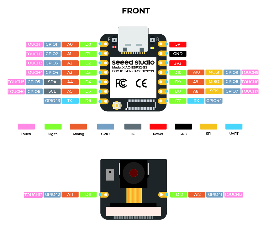
The following figure shows the pinout as configured by board definition (excluding the camera module).
@image html https://files.seeedstudio.com/wiki/SeeedStudio-XIAO-ESP32S3/img/2.jpg "Seeed Studio Xiao ESP32S3 Pinout" width=900px
The corresponding board schematic can be found here
Flashing the Device
Since the board does not have a USB-to-Serial chip, the easiest way to flash the board is using the USB Serial/JTAG interface. Just connect the board to your host computer and use the following command:
BOARD=seeedstudio-xiao-esp32s3 make flash ...
@note Usually the make system resets the board before flashing to enable the USB Serial/JTAG interface. In some special cases this reset does not work so that the programmer cannot connect to the board and the flashing is aborted with a timeout:
Serial port /dev/ttyACM0
Connecting...
...
serial.serialutil.SerialTimeoutException: Write timeout
This can happen for example if the board is not yet flashed with RIOT or the USB interface is used for another purpose. In this case, restart the board manually in download mode by pressing and releasing the RESET button while holding down the BOOT button. In download mode, the USB Serial/JTAG interface is always available.
For detailed information about ESP32-S3 as well as configuring and compiling RIOT for ESP32-S3 boards, see \ref esp32_riot.
Using STDIO
Since the board does not have a USB-to-Serial chip, the USB Serial/JTAG
interface is used by default for the STDIO (module stdio_usb_serial_jtag)
which provides an USB CDC ACM interface.
If the USB port is used by the USBUS stack or the tinyUSB stack, implicitly
the module stdio_cdc_acm or stdio_tinyusb_cdc_acm is used for the STDIO
via the USB CDC ACM interface.
Alternatively, the UART interface could be used with an external USB-to-Serial
adapter. Simply add stdio_uart to the list of used modules for this purpose:
BOARD=seeedstudio-xiao-esp32s3 USEMODULE=stdio_uart make flash ...